



Ultrasonic optical flaw detection allows visualization of internal defects (at a depth of about 1 mm) that are difficult to find using conventional ultrasonic testing. It can easily detect defects in joints and bonded surfaces in research and development processes involving the use and combination of various multi-component materials to increase strength and reduce weight.
MIV-X
Ultrasonic Optical Flaw Detector MAIVIS™
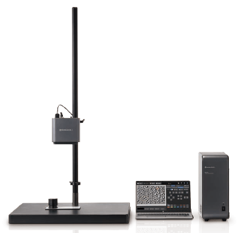
Make the invisible visible!
Ability to quickly and easily perform visual inspection of the examined surface
Visualization of cracks, voids, delamination, and other hidden defects that are usually impossible to inspect visually.
Thanks to Shimadzu Corporation’s patented light reflection technique, which combines an ultrasonic generator with a stroboscope, near-surface defects of the material, including delamination of bonding or adhesive surfaces of heterogeneous materials – paint, thermal sprays, and coatings, can be easily inspected without the need to destroy the sample.
You simply need to:
- Attach the ultrasonic generator to the sample and position the camera above the inspection surface.
- Start the device: ultrasonic waves will rapidly propagate through the material, and their interaction with defects will be clearly captured on video.
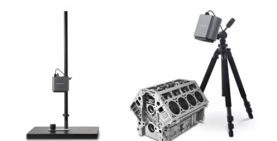
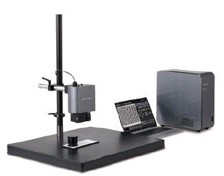
Using a camera stand allows for shooting both small and large objects.
Used in various industrial sectors

Types of inspections
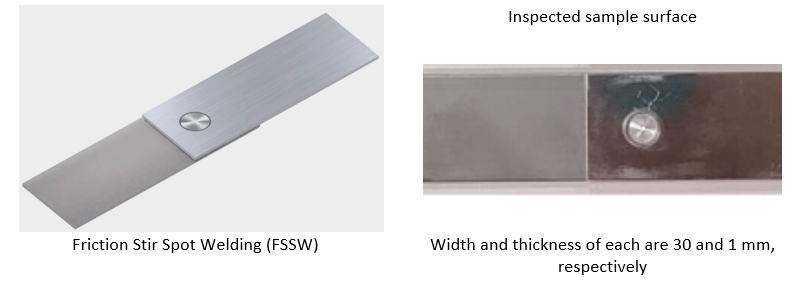
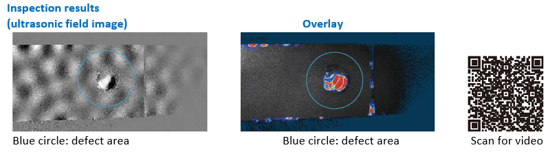
1. Inspection of poor bonding of dissimilar materials
Problems related to the delamination of bonded steel and aluminum surfaces, detected by a non-destructive method.
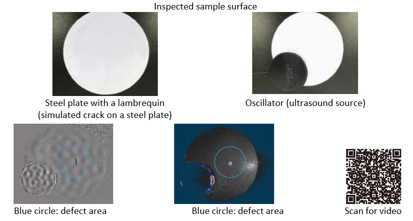
2. Inspection of a crack in the base material under a film (simulated coating)
A crack on the surface of the base material under a film (coating), which was invisible to the naked eye, is detected without peeling off the film.
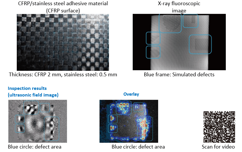
3. Inspection of adhesive surface delamination between CFRP and stainless steel
Artificially created delamination is detected by a non-destructive method. In addition, unconfirmed delamination is also detected using X-ray fluoroscopy (bottom right).
[Sample provided by: Nagoya Municipal Industrial Research Institute]
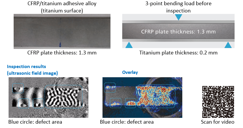
4. Inspection of adhesive surface delamination between carbon fiber and titanium alloy
A defect considered to be delamination due to a three-point bending load is detected by a non-destructive method. It is obvious that the delamination is significant in the center of the loaded area.
[Sample provided by: Kyushu University]
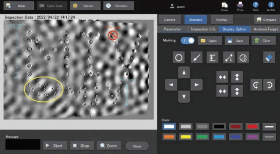
Inspection results screen
Measurement principle
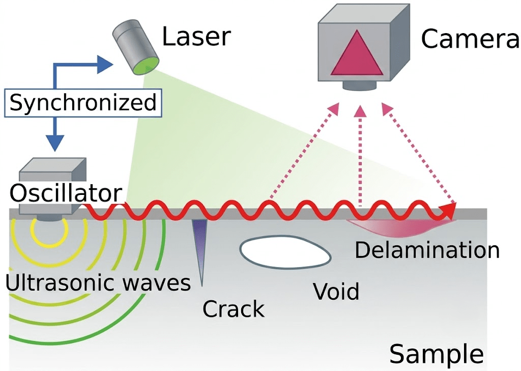
Using ultrasonic optical flaw detection technology, the displacement of the sample surface is optically detected and the propagation of the ultrasonic wave along the surface is observed.
To perform the inspection:
-
Saturate the sample with continuous ultrasonic vibrations.
-
Optically visualize microscopic out-of-plane surface displacement caused by wave propagation, using laser irradiation and a camera*.
-
Detect defects by observing disturbances in the propagation of the ultrasonic wave.
*Shimadzu’s patented light visualization technology combines spectrum-shift interferometry using ultrasonic vibration with stroboscopic technology. (Patented in Japan, China, and the USA)
Features of ultrasonic flaw detection
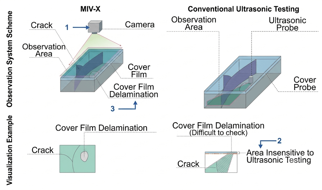
The MIV-X ultrasonic optical flaw detector allows viewing areas where ultrasonic testing (UT) is difficult.
Entrust non-destructive testing of surfaces and near-surfaces to MIV-X!
The following advantages:
1. The inspection zone is within a wide area of the camera’s field of view
2. Well suited for both general surface inspection and specific surface areas
3. No need to worry about the difference in acoustic impedance even when testing different types of materials
Useful functions

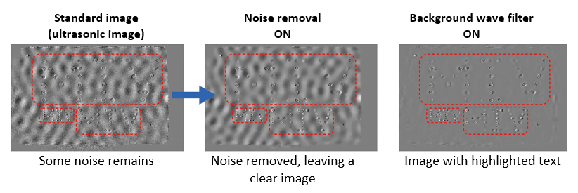
Noise removal function simplifies defect identification
Noise removal function simplifies defect identification
The letters “MIV” are engraved on the plate in three places (with engraved diameters of 1, 2, and 4 mm). (The diameter with the engraved MIV letters is indicated by a red frame).
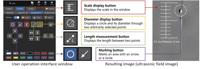
Size display and marking functions simplify identifying the position and dimensions of a defect
Optical zoom (option) for detecting small defects
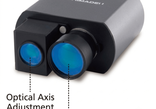
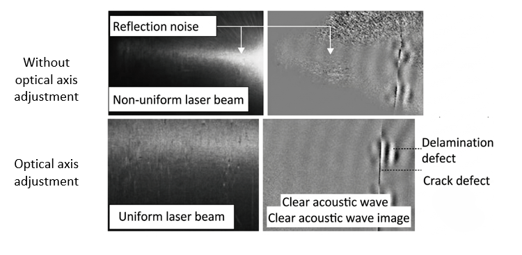
Reduces the minimum detection size by about half (from approx. 1 mm to 0.5 mm in diameter). It is also possible to adjust the optical axis of the laser, which improves the uniformity of irradiation.
Configuration
| MIV-X Universal Kit 331-30400-58 | |
| Camera Unit | 331-30340-11 |
| Control Unit | 331-30275-11 |
| Oscillator Unit | 331-30178-11 |
| Software | 331-30502 |
Personal computer, coupling, power cable, and camera stand are not included.
Technical Specifications
| Parameter | Specification |
| Purpose | Defect detection: near-surface voids and cracks, and delamination of bonded areas of multilayer materials |
| Materials suitable for testing | Metals, ceramics, composites, dissimilar joints, multi-component materials, etc. |
| Camera distance | 250 to 1000 mm |
| Field of view / Radius of curvature | Approx. 100×150 mm / R150 mm (camera distance 250 mm)
Approx. 200×300 mm / R300 mm (camera distance 500 mm) Approx. 400×600 mm / R600 mm (camera distance 1000 mm) |
| Minimum detection size | Approx. 1/100 of the inspection area (depending on the sample and inspection conditions). Camera distance 250 mm → Minimum detection size approx. 1 mm. |
| Testing time | Approx. 25 seconds or less (observation + analysis, excluding curing time) |
| Frequency | 20 kHz to 400 kHz |
| Laser safety (class) | IEC60825-1 Class 1, FDA 21 CFR Part 1040.10 Class 1, JIS C6802 Class 1 |
| Standard functions | Frequency scanning, analysis area specification, marking, size display, defect ratio calculation, complex multi-condition pattern analysis, noise removal, background wave filter, automatic search for inspection conditions, data storage/output |
| Power requirements | Single-phase power from 100 to 230 V, 250 VA. Power connection port on the control unit: IEC60320-C13 |
| Operating temperature | +10 to +30 ℃ |
| Dimensions / Weight | Camera unit: 180 mm (W) × 170 mm (D) × 88 mm (H); approx. 2.7 kg
Control unit: 165 mm (W) × 390 mm (D) × 406 mm (H); approx. 12 kg Oscillator: 60 mm (dia.) × 60 mm (H); approx. 0.9 kg |
Options
| Camera stand | 331-30450-42 | Maximum camera distance 1000 mm, with camera angle adjustment mechanism |
| Optical zoom kit | 331-30410-42 | Camera distance: 50 to 200 mm, field of view: approx. 28 × 42 mm (camera distance 50 mm), minimum detection size: 0.5 mm (depends on sample and inspection conditions) |